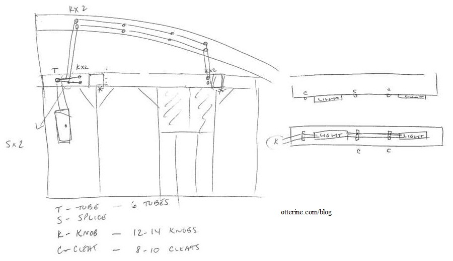
With the lighting plan in place, it’s time to start wiring — both the actual 12V dollhouse system and the fake knob and tube system. I started by drawing a rough sketch of where the knob and tube wiring would be placed. This also gave me a rough idea of how many of each piece I would need.

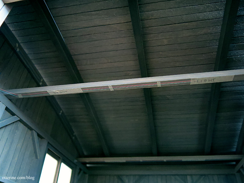
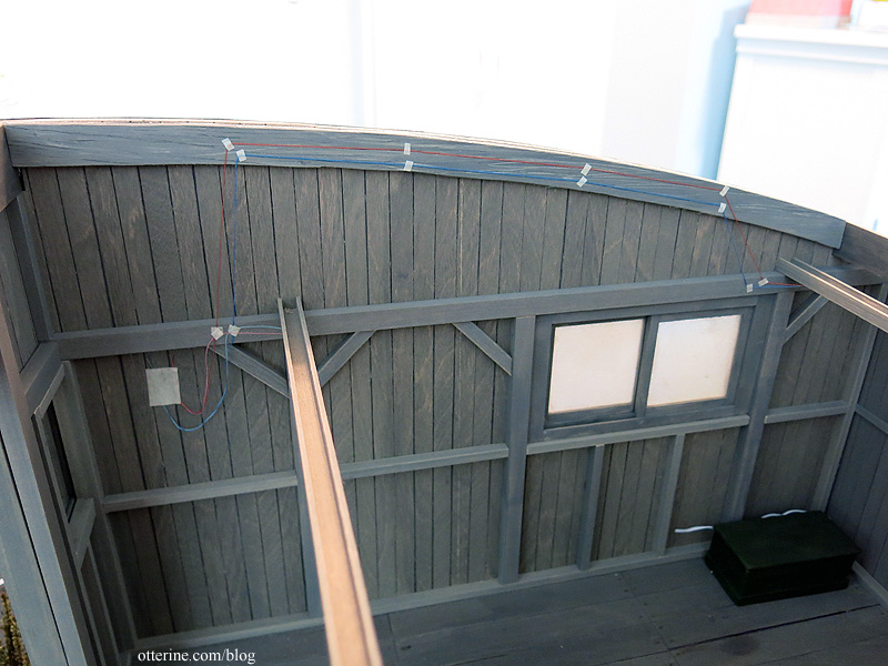
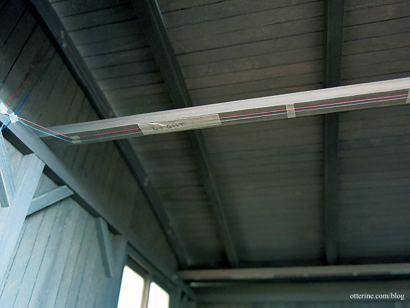
While I didn’t study antiquated electrical work in depth, the gist is I need two wires — one hot and one neutral — and you don’t want them to touch the building surfaces or each other. The final crochet thread wiring will come later since I’ll need to pull enough through to reach all of the areas where it is needed. Better to plot its course first. So, for right now, I am just taping some colored sewing thread in place as a trial run. I can then label by color for the length of thread I will need in each run.
From the fuse block, the wires will be spliced with one set to go directly up and the other set to hit the first cross beam. There’s a reason why the wires don’t start at the top, but that has to do with the exterior lead-in setup. I’ll get to that later.
I will drill holes in the cross beams and feed the 12V wires through the channels, splicing the lights on each beam to work as a single unit. In between those lights, I will need to add a wire path. One thing I showed you in the previous post but didn’t make were the cleats. These allow two wires to travel a parallel path. I’ll need to construct these as well.

I will space the knobs evenly along the top curved beam toward the second cross beam. Again, I’ve used small bits of tape to go through the whole path before making any permanent marks or holes. The wires then drop to the second beam.

I’m going to mull this over a bit now. I realized in looking at these pictures that I haven’t installed the support brackets for the cross beams, and that will interfere with this setup. I might also move the fuse box above the top horizontal beam instead of having it sit right below it. I have a few ideas, just need to sort them out. :]


